Demilade Sonuga's blog
All postsSome Mathematics I
In this post, we're going to begin infusing the game with physical laws.
Before we get on with doing so, we need a precise definition of what we're supposed to achieve. In the previous post, we took a look at the laws of motion and interaction that govern our game's cast and while that description is useful for getting an idea of what needs to be done, we need something more precise to actually get moving.
The Coordinate System
Cartesian
Before we can begin to deal with motion, we need a complete mathematical description of the game scene. While it would be nice to create a mathematical system we could use for this from scratch, we'll just make use of an existing one that is widely known, simple and intuitive: the Cartesian coordinate system.
I'm assuming that most people would be familiar with the Cartesian coordinate system. If you aren't, you should definitely check them out in the references.
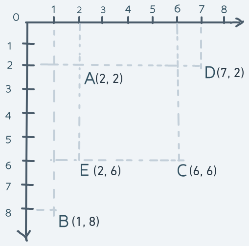
If you can remember, the CCS is a system in which each point in space is specified by a pair of numbers. More precisely:
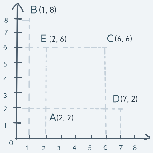
In the above diagram, the point in space labeled A has a coordinate of (2, 2). The point labeled B has a coordinate of (1, 8). The point labeled C has a coordinate of (6, 6). The point labeled D is at (7, 2) and the point labeled E is at (2, 6).
The horizontal line is the x-axis and the vertical line is the y-axis. Every single point in the space within those axes has a pair of (x, y) pairs that uniquely identify that point in space.
The origin is the point with coordinates (0, 0). It's the reference point from which all coordinates are relative. The numbers on the x-axis tell how far to the right of the origin a location is. The numbers on the y-axis tell how far upwards from the origin a location is.
For example, the point B which is at coordinate (1, 8) can be said to be 1 point to the right from the origin and 8 points upwards.
This simple arrangement gives us a full mathematical description of a two-dimensional space because every point in the space has a unique number pair.
Now, suppose that an object in the space is at point A and needs to get to point D and back. Achieving this is as simple as adding to the x coordinate of the object at point A until its coordinate matches D's coordinate. Then subtracting from the x coordinate until the object is back at point A. Precisely:
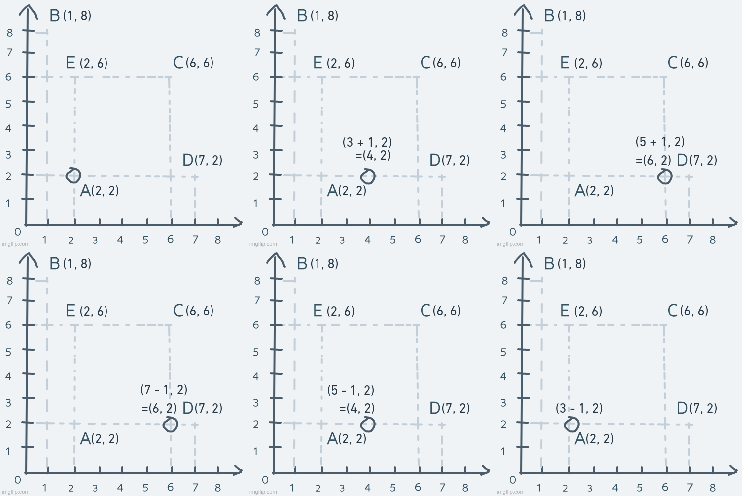
Just like that, we have horizontal motion.
Vertical motion is pretty similar, but instead of changing the x coordinate, it's the y coordinate we change. Consider an object's motion from point A up to point E and back:
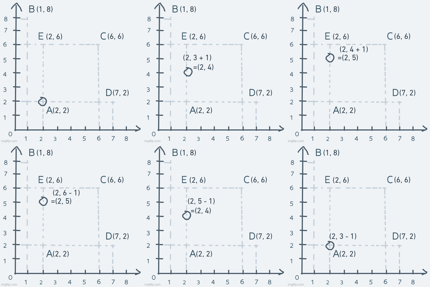
The y coordinate of the object is increased until its coordinate is equal to point E's coordinate. The object's coordinate is then decreased until it's equal to point A's.
And that's it for horizontal and vertical movement in this simple system.
As for diagonal movement, we change not just a single number in the coordinate, but both numbers. Suppose the object at point A moves diagonally to point C and back. The motion will look like this:
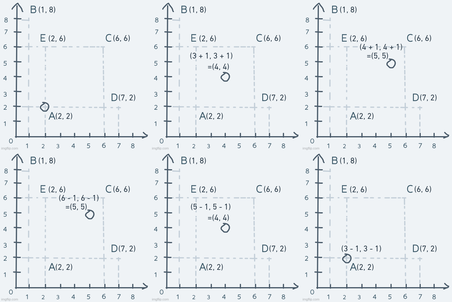
On each step, both the x and y parts of the coordinate are increased until the object's coordinate is equal to C's coordinate. To get back to A, both x and y are decreased continuously.
Ours
With the CCS, we have everything we need for good enough motion. But there is a slight problem here.
Our screen is modeled as a 2D array of pixels. 480 pixels high. 640 pixels wide. A screen model just like ours but with much fewer rows and pixels per row can be visualized like this:
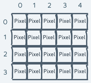
The above is a model of a screen with 4 rows and 5 pixels per row (in other words, 5 columns).
The problem lies where we try to mathematically describe the space on this screen with the Cartesian coordinate system.
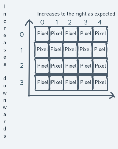
The index of the inner array (the column number) easily maps to become the numbers along the x-axis. But for the y-axis, the story is different. The row numbers (that is, the outer array indexes that identify which row of the screen we want to access) increase downwards. But in the CCS, the numbers along the y-axis decrease downwards.
To resolve this problem, there are a number of things we can do. One is to create some kind of mapping between the row index numbers and the y-axis numbers. Let's say to convert a row number into a y-axis number, you subtract the row number from the total number of rows. This way, the coordinate system for the screen will end up looking like this:
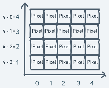
There are still some problems with this coordinate system but it can be made to work.
It also introduces new problems. If we have a screen variable screen and we want to access the pixel at
row 3 and column 1, we do screen[3][1]. But if what we have are the coordinates of that pixel, then
we have to do this: screen[4 - 1][1]. The reason for this is that with the mapping, the pixel at row
3 and column 1 will have a coordinate of (x = 4 - 3 = 1, y = 1).
This creates an asymmetry between the actual pixel location on the screen and its location in the coordinate system. Since we'll be doing a lot of drawing on the screen, this could get really confusing.
Another way we could approach this problem is to turn the CCS upside down. Usually, y increases upwards. But for the purpose of our game, we can redefine the numbers on the y-axis to increase downwards instead.
Imposing this coordinate system on our screen model:
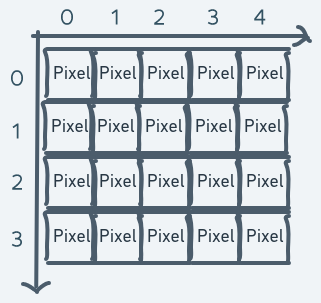
This way, the pixel location for any pixel is the same as the coordinate in the coordinate system. This will make understanding of the system much easier. But this has some consequences too.
In the previous section, it was specified that moving objects up requires an increase in the y coordinate moving them down requires a decrease. But in our new modified system, moving objects up requires a decrease in the y coordinate and moving them down requires an increase. Precisely:
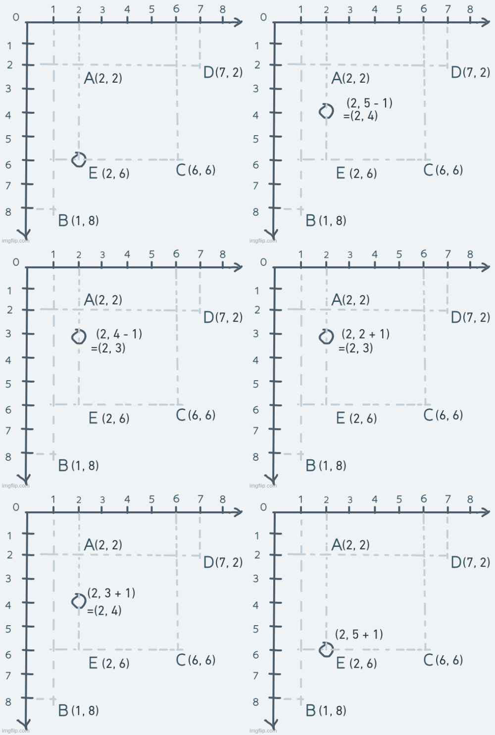
The same goes for the diagonal movements (any movement involving changes to both the x and y coordinates):
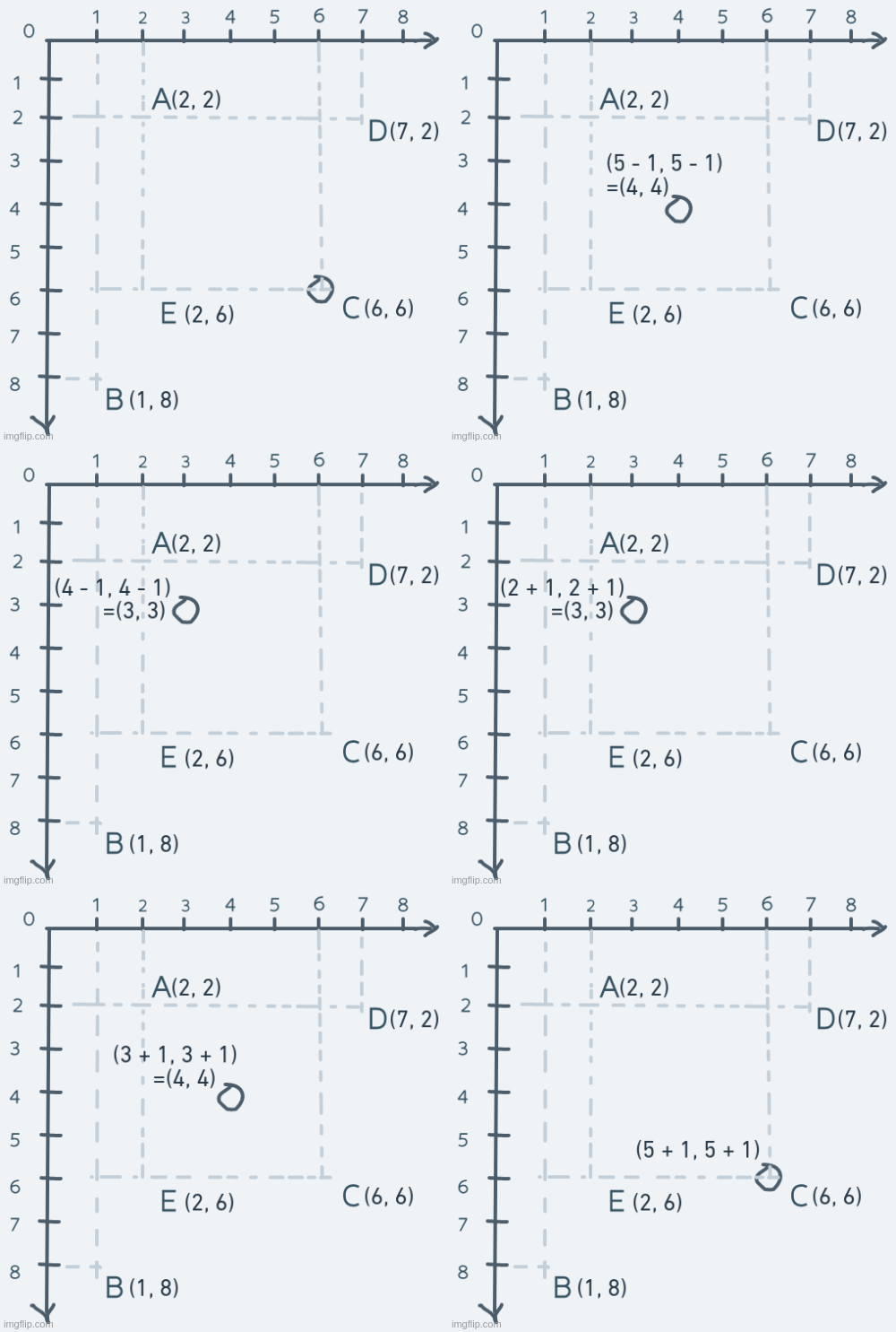
In the usual CCS, moving from C to A (decreasing the x and y coordinates) is a diagonal downward movement and A to C is diagonally upward.
But in this modified system, moving from C to A is diagonally upward and A to C is diagonally downward.
In our modified coordinate system, going up decreases y and going down increases y.
To retrieve the pixel at row y and column x on screen screen, you index like so: screen[y][x]. At this point,
in our modified coordinate system, the pixel at screen[y][x] will have its location as (x, y).
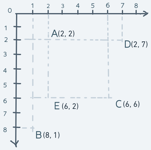
To make the location on the screen and the location in the coordinate system as identical as possible, coordinates in this system will be specified as (y, x) instead of the usual (x, y). This is to avoid confusion.
Now, our final coordinate system which we'll make use of in this game:
Altogether
Our game scene with our screen model looks like this:
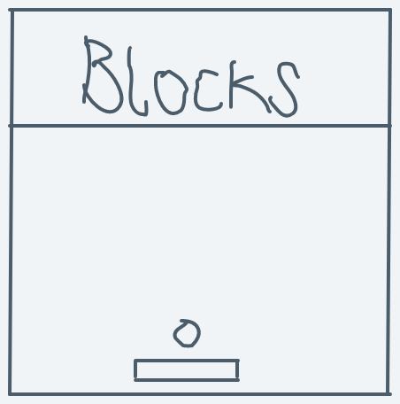
And our coordinate system looks like this:

Game scene meets coordinate system:
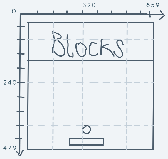
And what we have is a simple and complete mathematical description of space, locations in space and mechanisms for changing those locations.
Armed with our coordinate system, we can now get on with implementing motion.
Motion
Blocks
The blocks never move, so we don't have to bother with them.
Paddle
As for the paddle: it only moves horizontally. It is the only character that the player directly controls. We can define the left-arrow button on the keyboard as the button for moving the paddle to the left and the right-arrow button as the button for moving the paddle to the right.
Implementing this will be as simple as creating a new event hook for the keyboard and in the event handler function, move the paddle appropriately.
In game.rs
// ... Others
// DELETED: use crate::event_hook::{self, EventKind};
use crate::event_hook::{self, EventKind, EventInfo}; // NEW
use crate::machine::keyboard::{KeyEvent, KeyDirection, KeyCode}; // NEW
pub fn blasterball(screen: &Mutex<Option<&mut Screen>>) -> ! {
// ...Others
/* DELETED:
let initial_paddle_position = (
NO_OF_PIXELS_IN_A_COLUMN - paddle.height() - 10,
NO_OF_PIXELS_IN_A_ROW / 2 - 45
);
draw_bitmap(screen, &paddle, initial_paddle_position);
*/
// NEW:
let mut paddle_pos = (
NO_OF_PIXELS_IN_A_COLUMN - paddle.height() - 10,
NO_OF_PIXELS_IN_A_ROW / 2 - 45
);
draw_bitmap(screen, &paddle, paddle_pos);
let mut ball_pos = (
// DELETED: initial_paddle_position.0 - ball.height() - 5,
// DELETED: initial_paddle_position.1 + paddle.width() / 2 - 10
// NEW:
paddle_pos.0 - ball.height() - 5,
paddle_pos.1 + paddle.width() / 2 - 10
);
draw_bitmap(screen, &ball, ball_pos);
/* DELETED:
event_hook::hook_event(EventKind::Timer, BoxedFn::new(|_| {
erase_bitmap(screen, &ball, ball_pos);
ball_pos.0 -= 10;
draw_bitmap(screen, &ball, ball_pos);
}, allocator::get_allocator()));
*/
// NEW:
event_hook::hook_event(EventKind::Keyboard, BoxedFn::new(|info| {
if let EventInfo::Keyboard(KeyEvent { keycode, direction }) = info {
if direction == KeyDirection::Down {
if keycode == KeyCode::ArrowLeft {
erase_bitmap(screen, &paddle, paddle_pos);
paddle_pos.1 = paddle_pos.1.checked_sub(10)
.or(Some(0))
.unwrap();
draw_bitmap(screen, &paddle, paddle_pos);
} else if keycode == KeyCode::ArrowRight {
erase_bitmap(screen, &paddle, paddle_pos);
paddle_pos.1 += 10;
if paddle_pos.1 + paddle.width() > NO_OF_PIXELS_IN_A_ROW {
paddle_pos.1 = NO_OF_PIXELS_IN_A_ROW - paddle.width();
}
draw_bitmap(screen, &paddle, paddle_pos);
}
}
}
}, allocator::get_allocator()));
}We change the variable initial_paddle_position to paddle_pos because it no longer only holds the initial
position. When the player presses the left arrow key, the paddle's x position is decreased by 10 (a
small number that just seemed to make sense to me). A decrease in the x coordinate in our coordinate system
indicates a move to the left. When the player presses the right arrow key, the paddle's x position is increased,
resulting in a move to the right.
The checked_sub function is used for subtracting to avoid integer overflow errors (usize can't represent
a number lesser than 0).
For the right-arrow key code, a check is put in place to ensure that the paddle doesn't go offscreen.
For this to work, we have to implement the PartialEq trait for KeyCode to allow the equality check operation
to work on it.
In machine/keyboard.rs
// DELETED: #[derive(Debug, Clone, Copy)]
#[derive(Debug, Clone, Copy, PartialEq)] // NEW
pub enum KeyCode { /* Others */ }
If you run the game now and press the left arrow key, the paddle will correctly move to the left but it will also leave a trail.
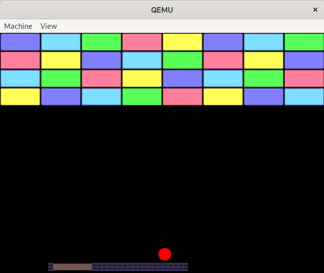
This outcome is not supposed to be. erase_bitmap ought to remove the whole bitmap from the screen, not
just part of it. This is a bug.
Some Quick Debugging
Now, how do we identify and get rid of this bug? Let's proceed by asking the right questions and answering them.
First, take a look at the code for moving the bitmap.
erase_bitmap(screen, &paddle, paddle_pos);
paddle_pos.1 = paddle_pos.1.checked_sub(10)
    .or(Some(0))
    .unwrap();
draw_bitmap(screen, &paddle, paddle_pos);
Why is the execution of this code leaving a trail of parts of the paddle bitmap? It seems like the problem should
lie with the erase_bitmap function because if that function was working as expected when draw_bitmap gets
called, it would be drawing the paddle again on a pure black background as if it had never been drawn before.
Take a look at the erase_bitmap function in display/bitmap.rs
pub fn erase_bitmap(screen: &Mutex<Option<&mut Screen>>, bitmap: &Bitmap, pos: (usize, usize)) {
    for row in 0..bitmap.width() {
        for col in 0..bitmap.height() {
            if row + pos.0 < NO_OF_PIXELS_IN_A_COLUMN && col + pos.1 < NO_OF_PIXELS_IN_A_ROW {
                screen.lock().as_mut().unwrap().pixels[row + pos.0][col + pos.1] = Pixel {
                    red: 0,
                    green: 0,
                    blue: 0,
                    reserved: 0
                };
            }
        }
    }
}
To understand what's going on here, you have to remember that the function assumes that the bitmap is
rectangular in shape and that the bitmap's position specified by pos is actually the position of its top left
corner.
erase_bitmap works by filling out the place where the bitmap was drawn on the screen with the color black.
The line for assigning the black-colored pixel into locations on the screen looks straightforward enough. Then what is the problem?
Taking a look at the for-loop, you'll notice that the first line says for row in 0..bitmap.width() {
and the second says for col in 0..bitmap.height() {. This is definitely wrong because the row number
is along the bitmap's height, not width. And the column number is along the bitmap's width, not height.
Correcting this becomes:
pub fn erase_bitmap(screen: &Mutex<Option<&mut Screen>>, bitmap: &Bitmap, pos: (usize, usize)) {
    // DELETED: for row in 0..bitmap.width() {
        // DELETED: for col in 0..bitmap.height() {
    for row in 0..bitmap.height() { // NEW
        for col in 0..bitmap.width() { // NEW
            if row + pos.0 < NO_OF_PIXELS_IN_A_COLUMN && col + pos.1 < NO_OF_PIXELS_IN_A_ROW {
                screen.lock().as_mut().unwrap().pixels[row + pos.0][col + pos.1] = Pixel {
                    red: 0,
                    green: 0,
                    blue: 0,
                    reserved: 0
                };
            }
        }
    }
}
And that's it for paddle movement.
Running the code now and moving the paddle looks like this:
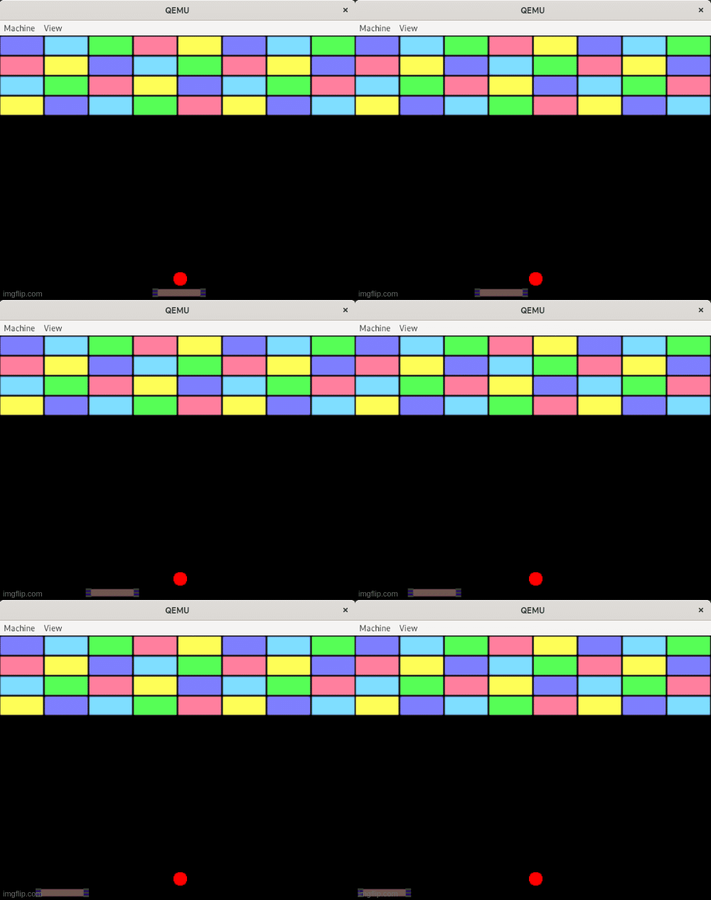
In the next post, we'll get to the star of the show: the ball, and its interaction with the rest of the environment.
Take Away
- In a (2D) Cartesian coordinate system, every point in space is uniquely identified by a pair of numbers (x, y) which are called coordinates.
- Motion (change of position) is simply the addition or subtraction of the coordinate numbers.
For the full code up to this point, go to the repo
In The Next Post
We'll get into the mathematics of the ball's motion and interaction.
References
- The Cartesian coordinate system: https://www.mathsisfun.com/data/cartesian-coordinates.html
- The Cartesian coordinate system: https://www.skillsyouneed.com/num/cartesian-coordinates.html
- The Cartesian coordinate system: https://en.wikipedia.org/wiki/Cartesian_coordinate_system